
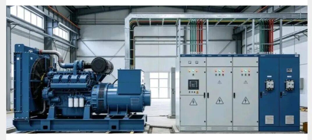
Paralleling of high‑voltage generator sets constitutes high‑risk live‑line high‑voltage work. Prior to construction, safety, technical and material preparations must be fully completed to prevent construction with unresolved defects.
I. Pre‑construction Preparation
Paralleling of high‑voltage generator sets constitutes high‑risk live‑line high‑voltage work. Prior to construction, safety, technical and material preparations must be fully completed to prevent construction with unresolved defects.
1. Technical Preparation
Familiarize yourself with drawings covering rated voltage, rated current, rotational speed, frequency and phase sequence of high‑voltage units, paralleling cabinets, high‑voltage switchgears and busbar systems. Clarify paralleling control logic, automatic synchronisation, protection setting values and closing interlock conditions. All generator sets participating in paralleling shall be identical in model, voltage, frequency and phase sequence.
2. Safety Preparation
Complete high‑voltage work permits and power‑cut operation permits. Conduct voltage verification for all high‑voltage equipment, fit earthing wires, hang warning signs and lock cabinets. Install rigid barriers around the work area to bar unauthorised personnel. Operators shall hold valid high‑voltage electrician certificates.
3. Equipment and Material Inspection
Inspect high‑voltage generators, high‑voltage paralleling control cabinets, high‑voltage circuit breakers, PT/CT transformers, synchronisation modules, communication control cables and secondary‑loop wiring for intact condition. Ensure insulating components are free from moisture, damage and carbonisation; instruments and protection devices shall be complete and functional.
4. Insulation Testing
Carry out insulation tests on generator stators, high‑voltage cables and high‑voltage cabinet busbars using a high‑voltage megohmmeter. Construction may only commence after insulation resistance values satisfy high‑voltage specifications; paralleling with insufficient insulation resistance is strictly prohibited.
II. Primary‑System Construction Procedures
1. Laying and Termination of High‑Voltage Cables
Lay cables from generator sets to high‑voltage paralleling cabinets and from paralleling cabinets to high‑voltage busbar cabinets in accordance with phase sequence A‑B‑C. Cable bending radii and fixing spacing shall comply with high‑voltage standards. Fabricate cable terminations to standard requirements with firm crimping and correct phase identification to eliminate risks of phase misalignment, poor connections and overheating.
2. Installation and Fixing of High‑Voltage Cabinets
Level and align paralleling control cabinets, high‑voltage incoming cabinets and bus‑tie cabinets. Fasten anchor bolts and ensure reliable cabinet earthing. The high‑voltage system shall adopt a dedicated TN‑S earthing system; cabinets, unit casings and neutral points shall each have independent earthing connections.
3. Verification of Primary Circuits
Verify unit by unit: consistent phase sequence, tight connections, busbars free of foreign objects, short‑circuits and earth contacts, and phase‑to‑phase clearance meeting high‑voltage safety distances. Check that circuit‑breaker closing/tripping mechanisms operate flexibly, energy storage functions normally, truck‑type units move smoothly, and interlock devices remain intact.
III. Secondary Control Loop and Paralleling System Wiring
1. Secondary Wiring for CT/PT Transformers
Complete secondary‑loop wiring for current and voltage transformers correctly. CT secondary circuits must never be open‑circuited; PT secondary circuits must never be short‑circuited. Ensure reliable secondary earthing.
2. Protection‑Loop Wiring
Connect protection loops for over‑voltage, under‑voltage, over‑current, overload, differential protection, zero‑sequence protection, over‑speed, under‑frequency and over‑frequency. Confirm correct wiring and proper position of protection plates.
3. Synchronisation Control‑System Wiring
Wire up automatic synchronisation modules, rotational‑speed signals, voltage sampling signals, closing output signals, unit start‑stop signals and paralleling communication cables. Ensure homologous sampling and signal synchronisation for every unit to prevent excessive deviation in voltage, frequency and phase angle during paralleling.
4. Interlock‑Logic Wiring
Implement wiring for non‑synchronised closing prohibition, bus‑tie interlock, mains‑generator mutual interlock and fault‑triggered off‑grid interlock to avoid false paralleling and reverse power feed.
IV. Post‑construction Overall Inspection
Recheck all wiring: verify primary and secondary loops point‑by‑point for correct wire numbers and secure connections.
Remove all tools, debris and copper scraps from cabinets to maintain clean interior conditions.
Re‑measure earth‑to‑frame insulation and phase‑to‑phase insulation of the high‑voltage system.
Confirm all earthing connections are sound, protection functions are activated and interlocks work properly.
Ensure all circuit breakers are in the open position with energy storage released.
V. No‑load Test for Individual Generator Sets (Unit‑by‑unit Test)
All individual units must pass acceptance before paralleling operations.
Start each high‑voltage generator set and run under no‑load conditions.
Monitor output voltage, frequency, rotational speed, three‑phase balance, unit vibration, temperature and abnormal noise.
Fine‑tune voltage‑regulation and speed‑regulation parameters so that voltage‑frequency characteristics of all units are broadly consistent.
Confirm no‑load operation has no alarms, abnormal temperature rise, voltage drift or fluctuation.
VI. Simulated Synchronisation Test (Off‑grid Dry Test)
Activate the automatic synchronisation device.
Perform simulated synchronisation tests between paired units: ‑ Verify allowable frequency difference ‑ Verify allowable voltage difference ‑ Verify phase‑angle difference returns to zero
Confirm the synchronisation module can capture signals normally, perform automatic speed and voltage adjustment, and wait for phase coincidence.
Verify that the non‑synchronisation blocking function takes effect and rejects closing when parameters exceed thresholds.
VII. No‑load Paralleling Operation (Core Procedure)
Run Unit 1 under no‑load first to stabilise voltage and frequency as the reference unit.
Enable automatic synchronisation mode for Unit 2 (the unit to be paralleled).
The system automatically adjusts speed and voltage to track parameters of the reference unit.
After frequency difference, voltage difference and phase‑angle difference all fall within permissible ranges, the synchronisation device sends a closing command automatically.
The circuit breaker closes, completing successful no‑load paralleling of the two units.
Observe post‑paralleling status: stable voltage and frequency, no circulating current, no oscillation and no alarms. Follow the same procedure to connect additional units one by one for multi‑unit paralleling.
VIII. Load‑sharing Commissioning
Activate automatic active‑power and reactive‑power load‑sharing after successful paralleling.
Gradually increase system load and observe performance of each unit: ‑ Balanced active‑power distribution ‑ Uniform reactive‑power distribution ‑ No condition where one unit runs heavily‑loaded while another runs lightly‑loaded
Fine‑tune speed‑regulation and voltage‑regulation gain parameters to bring load deviation within specification limits.
IX. On‑load Trial Operation Assessment
Operate at 50 % load for 30 minutes; check temperature, current, vibration and circulating current.
Operate at 80 % load for 1 hour; confirm no abnormal alarms or hot‑spots.
Run full‑load trial operation for 2 hours; ensure stable parameters and no spurious protection tripping.
Conduct simulated fault tests: loss‑of‑voltage, over‑current and over‑speed tests. Verify correct logic for automatic off‑grid, tripping and unit shutdown.
X. Normal De‑paralleling and Shutdown Procedures
Gradually reduce load on the unit to be de‑paralleled to minimum level.
Transfer its load to other operating units.
Trigger de‑paralleling via the paralleling system and open the circuit breaker.
Allow the unit to cool under no‑load for 3‑5 minutes before shutdown.
Direct load‑break disconnection for de‑paralleling is forbidden.
XI. Prohibited Practices for Construction and Paralleling
Do not perform paralleling with mismatched parameters (closing is forbidden when voltage, frequency, phase sequence or rotational speed are inconsistent).
Paralleling is forbidden if protections are not fully activated or interlocks malfunction.
Paralleling is forbidden with non‑compliant insulation.
Paralleling is forbidden in case of abnormal noise, excessive vibration or abnormal temperature rise.
Forbid manual forced non‑synchronised closing.
Forbid paralleling between mains supply and generator sets without interlock protection to prevent reverse power feed.
XII. Completion and Acceptance Documentation
Insulation test records
Individual unit test records
Synchronisation test records
Paralleling load‑sharing test records
Protection setting list and test reports
Trial‑operation records, concealed‑work records and wiring verification records